Standard Assembly Placement
Assemblies use a placement method very similar to the standard procedure used for other OpenPlant Modeler support. The main difference being that while the assembly is placed as one component, the assembly components are defined separately.
- Select an assembly option from the tool drawer.
-
Select the piping component to be supported.
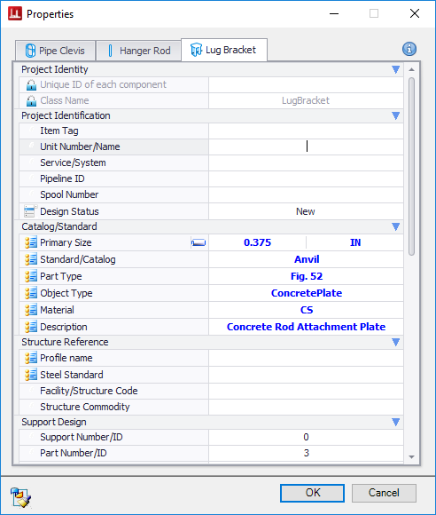
The Properties dialog opens.
- Select the specific assembly type from the Select Assembly dialog.
- Click OK.
-
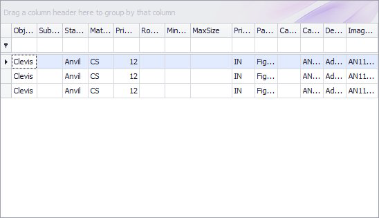
For each component you will need to define the Type and Size of the component from the Catalog section. When you click on one the field within this section a flyout grid displays listing the available sizes, types etc. for you to choose from:
Note: For some items, such as the Clevis, the size of the pipe selected is used to filter the options available for selection.
Once you have selected an item from the list, the catalog information is used to populate the remaining property fields if they were defined in the catalog.
-
Once the Properties dialog property values have been defined for all of the assembly components, click OK to place the assembly.
If both pipe and supporting steel components were selected at the beginning of the placement procedure, then the assembly will automatically be placed similar to the example below:
- Use the mouse and/or the Path Placement dialog to determine the precise location, rotation and stretch length if necessary for the assembly.


Save Assembly
When you have defined the property values for all of the assembly components, you have the option to save the assembly to the project database.